Shandong Yahong New Materials Technology Co., Ltd , https://www.okrooftile.com
The multi-stage pump housing is constructed from stainless steel, ensuring durability and resistance to corrosion. A series of impellers are mounted on a single pump shaft, working together in sequence to increase the pressure of the liquid as it passes through each stage. With every rotation, the centrifugal force generated by the impellers adds energy to the fluid, ultimately achieving high lift capabilities. This type of pump consists of four main components: the stator, rotor, bearings, and shaft seal. During operation, vibrations may occur due to loose bolts or an unbalanced rotor. To resolve this, it's essential to tighten all bolts and ensure the bearings are properly aligned.
When assembling the multi-stage pump, a thin layer of lead powder oil should be applied to the bolts and nuts for smoother installation. After placing the final impeller, measure the axial distance between the hub and the balance disc’s end face, then determine the sleeve’s axial dimension based on that measurement. The total clearance between the retaining sleeve and the impeller hub, along with the clearance between the sleeve and the balance disc hub, must be carefully considered. Since the pump starts operating from the front, the impeller parts are first exposed to higher-temperature media, causing thermal expansion at different times. An axial clearance of 0.3–0.5 mm is reserved to prevent the impeller and balance disc from expanding into each other, which could create excessive tensile stress on the shaft.
When installing the balance plate retainer ring, make sure one of the upper notches aligns with the interface of the balance water pipe. Failure to do so can block the balance water pipe, rendering the entire axial balancing system ineffective. Long rod bolts should only be tightened initially during assembly. Once the entire multi-stage pump is installed on-site, these bolts should be tightened according to pre-recorded data. Always operate symmetrically when tightening to avoid poor sealing between the pump sections.
The multi-stage pump is primarily composed of four key parts:
1. **Stator**: This includes the suction section, middle section, discharge section, and guide vanes. Tension bolts hold the sections together, forming the working chamber. Most multi-stage pumps are horizontally suctioned and vertically discharged. For oil field water injection, the inlet and outlet are usually vertical.
2. **Rotor**: Composed of the shaft, impellers, balance disc, and bushing. The balance disc helps manage the axial forces generated during operation.
3. **Bearings**: Made up of the bearing housing, bearings, and bearing gland. Bearings are typically lubricated with grease or light oil.
4. **Shaft Seal**: Uses soft packing, including a sealing body, packing, and water retaining ring. The water seal comes from pressurized water inside the pump, while DG-type pumps use external water supply for sealing.
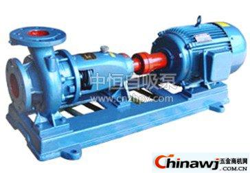
The pump is directly driven by a prime mover via an elastic coupling. When viewed from the motor side, the pump rotates clockwise, making it a horizontal, single-suction, multi-stage centrifugal pump. It is ideal for transporting clean water or liquids with similar properties. The medium temperature is typically below 80°C, suitable for applications like mine drainage, oil field water injection, and municipal water supply and drainage. Oil field pumps are made from different materials depending on the corrosiveness of the medium. Some models can handle temperatures up to 105°C, making them suitable for boiler feedwater systems.
For more information, check out our related guides on self-priming sewage pumps, flange butterfly valves, forged steel ball valves, high-pressure regulating valves, and electric butterfly valves.