With the development of computer-aided design (CAD) technology, 3D design software plays an increasingly important role in product design and manufacture because it can directly express the designer's intention, reduce the design process, improve the design efficiency. However, most of the current 3D design software, because of its complex design and use process, can not play the role of auxiliary design, but only as a three-dimensional drawing tool. Autodesk has recently developed the 3D design software Inventor. It emphasizes the top-down design process, with the functional requirements of the product, as the design orientation, and the design of related parts according to the assembly constraint relationship, which is consistent with the design concept in real life and can better support the engineer's design thinking. It represents the development direction of today's 3D design software, making it possible to directly carry out 3D design. Figure 1 2D graphics Figure 3 Flow chart of 3D parameterized standard parts library Cold Drawn Seamless Steel Pipe Cold Drawn Pipe,Precision Cs Seamless Pipe,Annealed Pipe Xinpengyuan Metal Manufacturing Co., Ltd , http://www.lc-steelpipe.com
I. Inventor Software Introduction Inventor software integrates 3D modeling, information management and support functions. As a three-dimensional design software, it uses a full Chinese operating system, has a good operating interface, easy to learn and use. Inventor is mainly composed of five modules: part modeling module, sheet metal module, assembly part module, view expression module, engineering drawing module, and five types of files corresponding to this: part file (ipt), sheet metal file (ipt), Part file (iam), expression view file (ipn), and engineering drawing file (idw). The functions of each module and its corresponding files are as follows: a single part design can be performed in the part environment, standard parts for assembly can be created, and 2D sketch geometry for layout can be created. Create a sheet metal part with a file type of part or sheet metal file: in the assembly part environment. Existing parts can be loaded into the part environment. And add assembly constraints, you can also create new parts in the assembly environment, the added assembly constraints are used to locate the parts, and can control the adaptive drive of the feature, the file type in the module is the component file; in the view expression module environment. You can define an exploded view of the part. Dynamic simulation of the assembly process is possible. The file type is an expression view file; in the engineering drawing module environment, you can create drawings of parts, assemblies, and expression views. Use one or more drawings to define a multi-angle view of a component. The file type is an engineering drawing file.
Second, Inventor provides graphic files for CAXA
Inventor is able to convert 3D models into 2D drawings. And can complete a variety of geometric tolerance labeling and partial view drawing. However, CAXA electronic drawing board has more powerful functions for drawing engineering drawings. It is necessary to input Inventor's 2D engineering drawing into CAXA software for editing and modification. The default extension of the 2D drawing file stored by Inventor is IDW. Other graphics software cannot directly read it and needs to convert the format. As we all know, CAXA can recognize graphic files in DWG/DXF format. The default file extension for CAXA boards is EXB. However, it is also possible to read graphic files in DWG/DXF format. Inventor when storing 2D drawings, select "Save as copy" in the "File" menu, save the type to DWG/DXF format, enter the file name, and select "Custom DWG/DXF" in "Options". Save after selecting "Done". It can be directly read by the CAXA electronic board and saved as an EXB file.
Third, the two-dimensional graphics are converted into a three-dimensional model
Use Inventor to convert CAXA electronic drawing drawings into 3D models. In the field of mechanical CAD, there are many 2D design software, such as AutoCAD, CAXA electronic board and so on. Inventor can easily convert 2D software drawings into 2D sketches through data conversion interface, and then realize 3D solid modeling by stretching, rotating and cutting.
The file formats supported by Inventor are: DXF, DWG, etc. Take the drawing of the small gear of DRAGONIV type dangerous robot as an example:
(l) Sometimes we are more familiar with CAXA electronic boards, so draw two-dimensional graphics in CAXA, as shown in Figure 1. 
(2) Then enter the file name and save it as a DWG/DXF file. In Inventor, click the "Open" button, then select the file and open it, and click Next in "File Input Options". Click Next in "Layer and Object Input Options". Select New Part in Input Target Options and the 2D sketch is generated when you are done.
(3) Rotating to generate a three-dimensional model (4) in the CAXA electronic board. Click the “Gear Drawing†tool and enter the gear parameters (modulus, number of teeth, pressure angle, displacement coefficient, crown height factor, etc.) to generate an overall tooth profile. Save as a DWG/DXF file.
(5) Select the lower plane of the above 3D model in Inventor, right click and select “New Sketchâ€, then click “Insert AutoCAD Fileâ€, select the file to open, and then click “Finishâ€.
(6) The gear sketch has been input into the above three-dimensional model and stretched to generate a three-dimensional pinion model. as shown in picture 2. 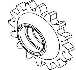
Figure 2 3D small sprocket model
This method is simple and fast for people familiar with CAXA, and is faster and more accurate than drawing directly in Inventor, especially the drawing of standard parts such as gears.
Fourth, the application of graphic file exchange
(1) Using Inventor to complete the transformation of 2D graphics to 3D models, which is convenient for assembly design, engineering analysis and simulation.
(2) Inventor 2D drawings can be converted to DWG/DXF files for modification or archiving on CAXA electronic boards. 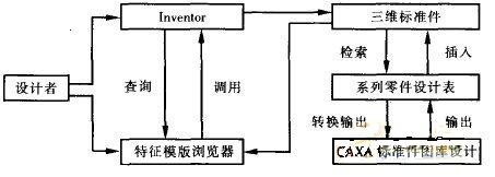
(3) Inventor uses CAXA electronic board data to build a three-dimensional parameterized standard parts library. Convert the data parameter name of the CAXA standard part into an EXCEL file, insert it into the standard part model as a series part design table, then save the standard part model and add its path to the reference path of the feature template browser in the Inventor system option. Standard parts can be called in the feature template in the form of a standard parts library. The flow chart of the 3D parameterized standard parts library is shown in Figure 3. The three-dimensional standard parts library established by the method of FIG. 3 has the advantages of convenience, quickness and avoiding repetitive labor. At the same time, no secondary development is required, and the Construction period is short.
V. Conclusion <br> <br> practice results show that this method of two-dimensional and three-dimensional software conversion software application is simple, easy to learn, easy to use, fast and convenient to provide two-dimensional or three-dimensional design for the designer. While using Inventor. Make full use of the rich software resources, you can get twice the result with half the effort. Greatly improve the efficiency of designers. Readers can also apply similar methods to Inventor and AutoCAD; Solidworks and CAXA; Solidworks and AutoCAD file exchange.