ZG High Efficiency Slurry Pump Naipu ZG series pumps are cantilevered,horizontal,centrifugal slurry pumps. They are used international advanced solid-liquid two-phase flow theory and were designed using the Minimum-Wear Principle. The flow parts of this pumps are suitable for the flow of state media for it's set shape, which reduces hydraulic loss of eddy and impact, both in pump and along the pipeline; so reduced friction of flow parts, lower noise and vibration of the pump translates into improved hydraulic efficiency.
Sugar Beet
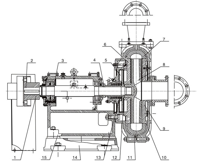
NP-ZG Slurry Pump Construction Component
Main Part Number At The Drawing
Materials of Construction
VOLUTE
IMPELLERS
BASE
EXPELLER
EXPELLER RING
SHAFT SLEEVE
SEALS
Standard
High Chrome Alloy
High Chrome Alloy
Cast Iron
Chrome Alloy
Chrome Alloy
SG Iron
Natural Rubber
Options
SG Iron
SG Iron
Mild Steel
SG Iron
SG Iron
EN56C
Nordel
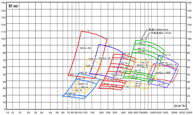
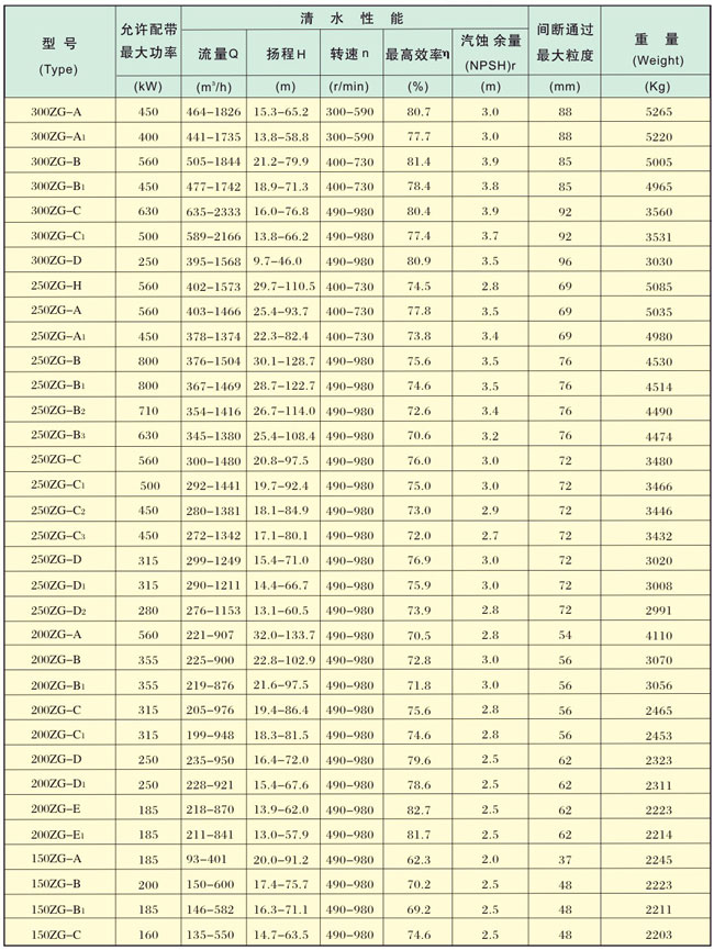
Note:Approximate performance for clear water,to be used for primary selection only.
ZG SLURRY PUMP PERFORMANCE PARAMETERS
ZG High Efficiency Slurry Pump,High Efficiency Slurry Pump,Ah Slurry Pump,High Head Slurry Pump Shijiazhuang Naipu Pump Co., Ltd. , https://www.naipu-pump.com
(1) Before installing the entire machine, it should be done:
1. Check whether the entire machine has complete components and whether the position is correct.
2. If it is against a wall or close to other buildings, there should be a relatively loose equipment maintenance and maintenance space (usually about one meter) during installation.
3. Leave a wide space for raw material stacking.
4. Leave a site for convenient stacking and transportation of finished products.
5. There should be flat concrete foundation (length 11000X??1500X 200mm thick)
(2) Install the host
Use the expansion bolts of M12 to fix the four bases of the main machine to the concrete foundation (Note: the main machine must be flattened): Then fix the blanking rack, pay attention to ensuring that the center of the two grooves in the traction wheel, the center of the trolley fixing round knife in the trolley should be on the same straight line, and the blanking rack should be about 20mm lower than the main machine.
(3) Come on
Add 1kg of gear oil into the traction box, and inject 40-50kg of anti-wear hydraulic oil into the hydraulic tank (note 45# for summer and 32# for winter). Straighten the front and rear bearings of the frame, and straighten the wheel bearings are every two shifts - butter.
(4) Turn on the power
Place the electrical control box in a place that is easy to operate and without vibration on the opposite side of the main unit.
Open the electrical control box
Connect the straightening traction motor cable to the "straightening" terminal (the two motors have been connected together when they leave the factory)
Connect the cut motor cable to the "hydraulic terminal"
Connect the solenoid reversing valve cable to the "solenoid valve terminal (the common wire is 0 positions)
After careful inspection, connect the 380 volt power cord to the "power supply terminal"
Note: The power cord should not be less than 6mm2 international copper cables within 50m
2. Working principle and adjustment method of hydraulic station of steel bar straightening cutting machine
During the hydraulic station, a 4KW/5.5KW motor is powered by a 4KW/5.5KW motor, which drives a blade pump with the model Y13-D25 to supply oil. The hydraulic oil output from the blade pump enters the integrated block and enters the solenoid reversing valve. When it is not working, the oil circuit does not form pressure, and it is directly returned to the oil tank by the solenoid reversing valve (installed above the integrated block). During work, under the command of the electric control box, the hydraulic oil (due to the effect of the safety pressure control valve, the oil circuit forms a fixed pressure, generally 6- 8MPa can be installed from the front of the shock-resistant pressure gauge and integrated block. When the high-pressure oil pipe in the tool is shown in front of the high-pressure oil pipe, the cylinder piston rod is pushed out (the tool is cut off) for about 0.17 seconds. The time cutter in the electrical control box is automatically controlled, and the electromagnetic reversing valve is automatically reversed. The hydraulic oil enters the high-pressure oil pipe in the tool returns to the tool, and pushes the cylinder piston rod in (the tool is returned to the tool is reset). The pressure is adjusted by the safety pressure control valve. The pressure should not be adjusted too high. It is better to cut the steel bars. Too large will increase the motor load and seriously damage the motor. The cut-off is generally 0.12 seconds.
This setting has been adjusted when leaving the factory. If it is not necessary or professional, please do not transfer it at will to prevent damage to the parts.
3. No-load test machine
Turn on the power supply and place the power switch in the electronic control box in the on position. At this time, the indicator light on the panel is on. Check the voltmeter. The voltage should be 380 soil and 20 volts. After correct, press the "Hydraulic On" button. At this time, the hydraulic motor starts and check the steering of the hydraulic motor (if reversed, please change the wire head). After correct, press the "click in" button. After the traction and straightening motor is normal, press the "Shut off" button to check whether it is normal. Only after normal can the debugging work be done.
Test machine: Pull out the wire plate for a section and manually pre-adjust about 2 meters. Release the handle wheel, place the spring press plate in the accessories box above the slider, and install the pre-adjusted wire in the order of wear-resistant sleeve of the feed port - push box traction wheel - traction box traction wheel - round cutter hole. Note: After the curve is adjusted, the screws must be locked and not loosened. The number of points required by the person is input, and the length is set, and then the machine can be turned on.
Typical Applications---
Electric Power
Constructional Material
Mine Coal
Coal washing
Sand Reclamation

2 Shaft
3 Bearing Housing
4 Disassembly Ring
5 Expeller
6 Rear Liner Plate
7 Volute Casing
8 Impeller
10 Front Casing
11 Rear Casing
12 Stuffing Box
13 Water Seal
14 Base
15 Support
or
SG Iron
or
SG Iron
Fabricated
Ferralium
Hasteloy C
Ceramic
Stellite
Chrome Oxide
Neoprene
Viton
Butyl
EPDM
ZG SLURRY PUMP SELECTION CHART


1. Installation and debugging of CNC steel bar straightening and cutting machine
1 Coupling
9 Front Liner Plate