The grounding of the photovoltaic power generation system is very important, and the requirements for grounding are also very high. If the grounding is not reliable, it may cause lightning damage to electrical equipment such as inverters. The voltage measurement is inaccurate and susceptible to external interference, which will cause the inverter to work abnormally. Therefore, after the installation is completed, it must be tested correctly to ensure that the protection meets the specifications.
Grounding types and requirements include the following. First, lightning protection grounding: including lightning rod (band), down conductor, grounding body, etc., the grounding resistance is required to be less than 10 ohms, and it is best to consider setting a separate grounding body; second, safety protection grounding, working grounding, shielding grounding, etc .: requirements Ground resistance is less than or equal to 4 ohms. When the four grounds of safety protection grounding, working grounding, shielding grounding and lightning protection grounding share a group of grounding devices, the grounding resistance is determined according to the minimum value of 4 ohms. Share a group of grounding devices, the grounding resistance should not be greater than the minimum value.
After the grounding system is completed, it is critical to measure the grounding resistance correctly. However, the grounding resistance is not necessarily the same as our common resistance components. It cannot be measured with an ordinary multimeter. Special instruments must be used. There are usually the following measurement methods: two-wire method, three-wire method, four-wire method, single-clamp method and double-clamp method. Each has its own characteristics. In actual measurement, try to choose the correct way to make the measurement results accurate.
First, the voltage method
The voltage method includes: the two-wire method, the three-wire method, and the four-wire method are all voltage methods. The working principle of the voltage method is to apply an alternating current I to the ground electrode C and the electrode E, and then measure the potential difference V between the points E and P, and the ground resistance R is equal to V / I. The specific principle is shown in the figure below.
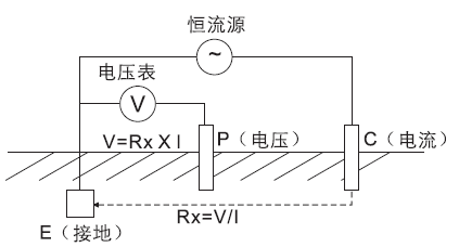
"Notes": There must be two ground rods: an auxiliary electrode and a detection electrode. The distance between each grounding electrode is not less than 20 meters. The grounding electrodes should be hit to a depth of about 1.5 meters and arranged in a row. The soil should be moist. If it is dry land, or enough water should be added to the stone and sand to test.
The four-wire method is basically the same as the three-wire method. It replaces the three-wire method when measuring low ground resistance and eliminating the effect of measuring cable resistance on the measurement results. Four small-sized electrodes are inserted into the ground at the same depth and equal distance (straight line). And take measurements. This method has the highest accuracy among all ground resistance measurement methods.
Second, the current method
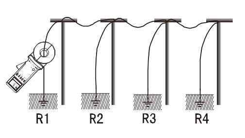
The current method includes: the single-clamp method and the double-clamp method are both current methods. The current method can measure resistance without disconnecting the ground system. No need to disconnect the down conductor, no auxiliary electrode, fast, simple and reliable, and also includes the grounding and overall ground connection resistance in the measurement.
The basic principle of a clamp-on ground resistance tester for measuring ground resistance is to measure loop resistance. The jaw part of the clamp meter is composed of voltage coil and current coil. The voltage coil provides an excitation signal and induces a potential E on the circuit under test. Under the action of electric potential E, current I will be generated in the measured circuit. The Clamp Meter measures E and I to get the measured resistance R = E / I.
Single-clamp method: measure the grounding resistance of each grounding point in multi-point grounding, and can not disconnect the grounding connection to prevent danger. It is suitable for multi-point grounding, it can not be disconnected, measure the resistance of each grounding point. The method is to use a current clamp to monitor the current on the measured ground point.
Double clamp method: multi-point grounding, no auxiliary ground piles, single grounding measurement. The method is to use a current clamp to connect to the corresponding socket, and clamp the two clamps on the ground conductor, and the distance between the two clamps should be greater than 0.25 meters.
to sum up
If the worker wants to do his best, he must first sharpen his weapon. After the grounding network is installed, the correct method and instrument must be used to measure the result to ensure the quality of the project, otherwise it will be in vain.
Disc or Cylinder Magnet
Neodymium Disc Magnet ,Neodymium Cylinder Magnet ,Round Door Magnet,Big Circle Magnets
Ningbo Besten Magnet Co., Ltd. , https://www.bestenmagnets.com