Ductile manhole cover,Iron Manhole Covers, Ductile Sewer manhole cover, Ductile Power Manhole cover, Ductile Electric Manhole Cover Runchun Casting (Zhoushan) Co., Ltd. , https://www.en124casting.com
With the rapid advancement of the domestic aviation industry, conventional three-axis machine tools are no longer sufficient to meet the growing demand for diverse product processing. As a result, more complex multi-axis machining technology has become the standard in modern manufacturing. Our company uses VERICUT simulation software, which originally only supports three-axis machining. The challenge is how to simulate multi-axis machining using this software based on an existing three-axis machine tool setup. This article explores how we achieved multi-axis simulation, specifically focusing on the A-axis.
**1. Research on Three-Axis Machine Tool Simulation**
We started by opening VERICUT 6.1 and creating a new project. We added the original FANUC three-axis control system and machine tool module under the Setup-CNC Machine section. By navigating the component tree, we could view all parts of a typical three-axis machine, as shown in Figure 1.
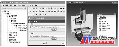
The simulation of three-axis parts relies on the manufacturer’s pre-defined control system and machine tool module. We added blanks, coordinates, tools, and programs to complete the simulation. However, this setup is limited to three-axis parts and cannot support multi-axis machining simulations.
**2. Adding Machine Components for Multi-Axis Simulation**
To simulate multi-axis machining, we needed to add a fourth axis (A-axis) to the existing three-axis machine model. Before doing so, it was essential to understand the motion relationships between different components. Through analysis of the three-axis machine, we determined that the A-axis should be attached to the X-axis. Using the component tree, we added an A-rotation attribute to the X-axis, as shown in Figure 2.
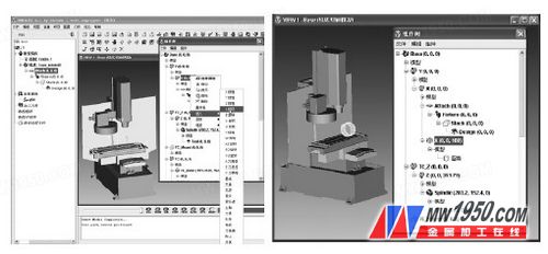
Next, we added a part that rotates around the X-axis. By utilizing movement and rotation functions within the software, we positioned the newly added component to match the real-world machine tool, ensuring accurate simulation.
**Note:** The position of the added machine part must align with the A-axis rotation feature.
**3. Testing the A-Axis Simulation**
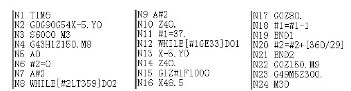
After successfully adding the A-axis assembly, we tested the newly introduced components. A simple CNC program was used for testing, as shown in Figure 3.
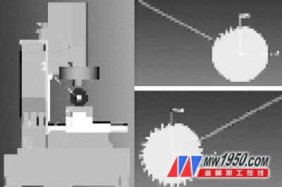
Once the machine configuration, tools, programs, coordinates, and parts were set up, we initiated the simulation. The results confirmed that VERICUT now supports A-axis simulation for a four-axis machine, as shown in Figure 4.
**4. Conclusion**
Through our exploration, we successfully implemented A-axis simulation for a four-axis machine tool using VERICUT. This significantly reduces the risk of part or machine damage due to programming errors, minimizes on-site debugging time, and enhances overall production efficiency. Additionally, this experience provides valuable insights for simulating other multi-axis CNC machining centers in the future.